
MEP Challenges in a Brown Field Project: A Case Study
By Akshay Khare
This is in continuation to the case study of transformation of an IT park to a hospital. 'Challenges in Core Shell Brown Field Project - A Case Study'[1] , discussed the architectural and structural standpoint challenges one encounters in a brown field hospital project. In this part, the focus will shift towards one of the integral part of hospital project - MEP and its allied subsidiaries.
Let us first understand the key difference between a brown field 'regular commercial project' and a brown field 'hospital project'. It is imperative to understand that a hospital project typically warrants following attributes in MEP - (a) Number of engineering services and sub-services are comparatively more, what with systems such as Patient Call, Nurse Call coming into play. (b) Number of variables becomes much more since each department (and sometimes rooms) has its own specific requirements, both statutory and functional. (c) The critical application demands much more precision as well as adherence to the health care guidelines.
As it is, creating a robust MEP system for a hospital is challenging enough but the challenge goes a notch higher when this is to be done for a brown field project. Here we are talking about converting an IT park to a multi-specialty hospital— if you ask any MEP designer, they would unanimously agree that both are the extreme ends of the spectrum. In this case many systems either had to be augmented to meet the requirement or were completely done away with. Case in point is the HVAC system which is primarily one dimensional for IT projects but when it comes to hospital it almost becomes a complex sub-project in itself with multiple levels and intricacies being involved. Likewise 'Low Voltage System' - the backbone of communication in any healthcare setup, consists of about twelve major entities which truly gives it a multi-dimensional form. (More on this in later on.)
Thus, a superlative designing, planning and execution of MEP system is of foremost value.
Major Challenges & Mitigation
In the following passage, endeavor will be to highlight the major challenges intrinsic to this case study while consciously staying away from the regular problems of project management.
Structure: There were innate limitations to the way one could plan in the existing structure. The idea was to keep the alterations to the bare minimum.
The structure was not initially designed for the new requirements - medical equipment and engineering equipment loading. A comprehensive list of all such equipment (even the ceiling suspended AHUs) was drawn in accordance to their degree of criticality. Slabs were locally strengthen wherever required (by network of MS beams) to bear the load of heavy equipment. For lesser loads like those of AHUs etc. locations in a given floor plate were carefully (precisely) chosen and validated before the detailed drawings were made.
The addition of reinforcing beams to the superstructure resulted in quite low heights especially on Ground and Mezzanine floors, which meant that the air-conditioning ducts could not run above the false ceiling. At the same time it was important to regain a respectable false ceiling height in most of these areas. Further compounding the problem was the fact that the furnished drawings from the previous owner did not always give accurate dimensions of the structural elements, these small deviations might not have an impact in other areas but in areas, such as ground floor where even a margin of 50 mm was crucial.
So, taking one area/department at a time we would go to the site and assess and record the actual site dimensions. After compiling all the actual site data we segregated the critical areas from the non-critical ones. Then we removed ducting system from the latter and designated individual cassette units to them. Though the net gain in effective height was much reduced as the chilled water horizontal pipes (especially in passages) replaced ducts but still we were able to gain 75-100 mm which went a long way in achieving a respectable finished ceiling height. The non-critical areas of Ground floor constituted about 75-80% of the floor, for rest of the area i.e. 'critical areas' the same solution could not be applied as dedicated AHUs with ducting system was a necessity. To overcome the problem at hand we identified alternative routes (clear of common areas. passages & patient occupancy), used aesthetical treatment like drop down ceilings/pelmets etc. to cover any oddity.
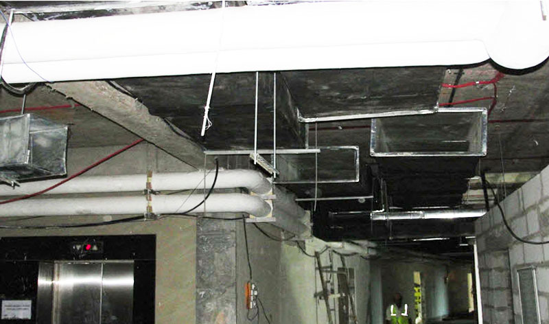
Figure 1 Co-ordinated services' lines passing through lift lobby and passage.
Having learned our lesson on the lower two floors, we decided to repeat similar exercise on other floors as well and proceeded to record actual structural dimensions and uses this data for preparation of construction drawings.
Space Planning: From MEP perspective, we were concerned with mainly two things - planning of engineering yard and the spaces in a given floor plate. Both were planned in close co-ordination with the architecture team.
For planning of the first part, existing engineering yards were studied minutely in conjunction to the new design requirements. Earlier there was no HVAC plant room since the previous facility did not have centralized air-conditioning. The panel room originally in basement had become redundant owing to greater heights of new panels, larger space requirement and possibility of water logging in basement during monsoon. Additionally, the critical application demanded a substantial power back-up system which led to the requirement of two huge DGs. Generally, DGs can be kept in the open with acoustic enclosure or they can be housed inside a dedicated building. Construing the techno-commercial aspects of both we finally opted for the latter, partly due to the construction of a new service building. Thus the idea of a dedicated Service yard was conceptualized. This building was designed to house HVAC, HT & LT, D.G yards at different levels with transformer yard just abutting the building. This just not solved our space planning problem but also went a long way in saving installation costs such as cabling and providing better maintenance options.
The pump rooms had to kept near the underground tanks for obvious reasons. Still Plumbing pump room had to be augmented and Fire pump room had to be constructed anew for varying technical and design issues.

Figure 2 Plumbing pump room was augmented to meet new requirement.
The floor spaces viz. electrical rooms and AHU rooms were planned in those areas where UDL was good enough. The electrical rooms were split into three rooms at each floor so as to have two of them at the extreme ends of a given floor plate and one at the middle. This ensures that the floor panels did not get big and heavy at a single location. In case of AHU rooms, the structural strength was validated at the time of departmental planning itself.

Figure 3 UPS room strategically chosen to bear load of battery units, panels & UPS.
Service ducts: At the very inception of planning we were somewhat wary about the fact that the available vertical ducts would not be sufficient for the new requirement. We made a list comprising of 'available vs required' shafts to comprehend better. The auxiliary details of existing shafts viz. internal dimensions, locations of shear sections, throughout or otherwise etc. were also noted down in detail.
Taking cognizance of the above it was clear that additional shafts were the need of the hour. We have seen in the last part that typical toilets had to be shifted to the peripheral side of the building because of structural constraints and lack of feasibility of creating vertical shafts in the slabs. To cater to this demand additional shafts were created by introducing artificial elements (boxing/troughs) in the elevation scheme. These elements (or external ducts) while serving their primary purpose also had to jive with the overall elevation and not end up looking like an incongruity. This was made possible by having symmetrical intervals between the elements and the careful selection of facade material to enhance the look.
The existing shafts were designated as per the new requirement. Some of the large ones had to be divided into two or three shafts to suit the requirement. Vertical partitions (fire and moisture resistant) had to be created to adhere to the prevalent norms, which was a time and cost consuming work. In these multi-usage shafts, one of the obstacle faced was to co-ordinate termination of horizontal lines into these shafts without interfering with each other.
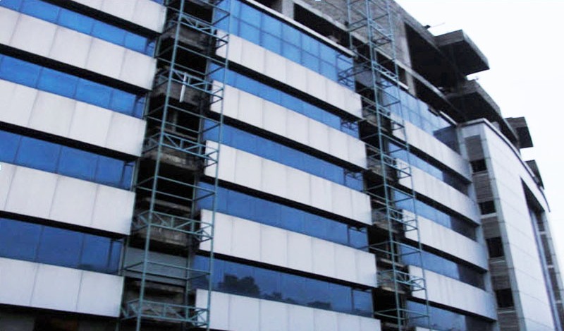
Figure 5 Added service shafts on the facade.
Building envelope: The new vision mandated the building facade to be reinvented. Changes in factors such as glass type, exposed surface area, wall thickness etc. resulted in change in the engineering design calculations. One example of this is the change from Single Glazing Unit to Double Glazing Unit which warranted change in the heat load calculation.
Secondly, with the new elevation design, wall openings at external face of the building (for services termination) more often than not, became impossible. This was taken care by the strategically placed artificial elements (as explained in the previous point).
Drainage system: This is one service where one doesn't gets the leverage of using pressurized lines and one has to follow the natural gradient, coupled up with the fact that in a hospital plumbing points are often scattered across the floor plate (instead of typically stacked), it becomes a considerable challenge.

Figure 6 Drain points are scattered across the floor plate.
By now we are well aware that how external shafts were created for the peripheral toilets. For rest of the scattered points - locations had to be shifted to the nearest shaft or egress point which inadvertently caused reorientation of that particular space.
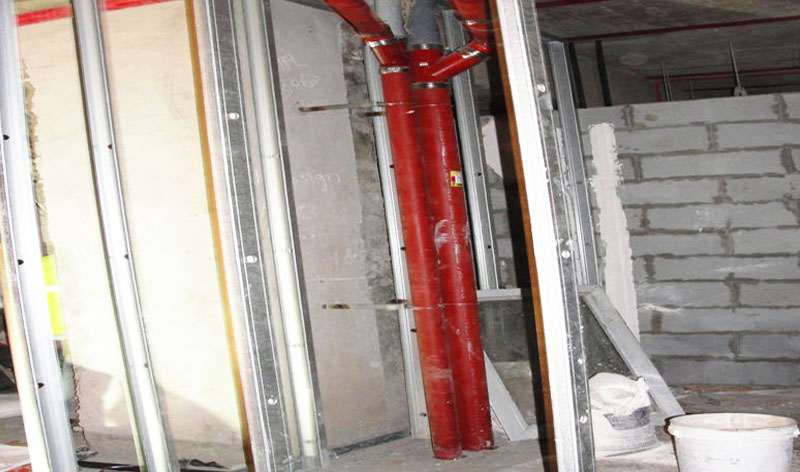
Figure 7 An additional plumbing shaft was created as there was no nearby egress point.
One major problem faced was the drainage methodology in the basement level. As per the new design there were numerous change rooms & staff toilets along with laundry planned in the basement. But putting new drain lines and sumps was almost impossible by cutting through the existing raft/slab. This was countered by raising all the wet areas of the basement to create that extra height for routing the drain pipes to the nearby external drainage network. The conventional method of draining out of sewage and waste is to connect these pipes to a close by collection chamber using natural gradient. Then the waste is being pumped out to the external drainage network. This method is costlier and a maintenance headache. Instead we used special pumping sets (pump with attached chamber units) to pump sewage to the external drainage network, which saved a lot of money, work and time.
Heights: Though the true heights of slabs and beam sections were captured for almost all the areas, still there were lots of instances where services lines, if executed as per the drawings, would have caused lower ceiling heights than what was desired. This meant that before preparing co-ordination or construction drawings for a given area, we would visit the area - review the possible cluster area (instances of crossing), explore the 2-3 possibilities which presented itself before us and then finalize the more viable option. Mock-ups were made of the co-ordinated sections and then they were copied to the drawings for one last review, before being expanded into the full fledged drawings. This took time and often construction drawings of one floor (roughly 25000 sq.ft) along with co-ordination drawings would get finalized not earlier than a month.

Figure 8 A typical view of services running through a corridor
The last stand - Execution
No matter how much planning or designing one may put into this type of project, it can quickly turn into a debacle if the co-ordination during execution at all levels is not carried out with relentless precision. As can be inferred by now, there were constraints all along - be it structural, space, heights or architectural, so the impetus was very much on the effectiveness of co-ordination between construction agencies, consultants (structural, architects, MEP, landscaping, medical etc.), end users, owners and project manager.
From the outset, following measures were taken to minimize bottlenecks:-
Process of obtaining statutory approvals like 'Change of Use', 'Fire NOC' etc. was initiated at the very inception.
Impetus was given to the construction agencies who had prior experience of brown field projects of similar magnitude.
A customized schedule was made to capture the specifics of this project with co-ordination meeting held at every fortnight between all stakeholders to track and scrutinize the project progress.
Medical equipment vendor selection was done right at the beginning to factor in their respective pre-requisites.
Mock-up of typical rooms such as OPDs, IPDs & typical toilets were finalized during the initial stages so that head start could be given for purchasing of fixtures, finishing materials etc.
Notwithstanding some minor hiccups and gaps, the system was successfully commissioned during the last fall and the hospital as a whole has come out beautifully, a far cry from a depleted IT park building three years go.
Yet another addition to the growing Indian healthcare story.
Author
Akshay Khare, Asst. Project Manager, Hosmac India
A mechanical engineer by qualification, Akshay Khare has 9 years of experience in the PMC field.